
Signed Adder using Verilog
Concepts to be covered:
- Signed numbers
- Signed Magnitude adder
- Verilog code for signed adder
- RTL view
- Testing circuit for signed adder
- Stimulation
1. Signed numbers
A signed integer can be represented in a Signed-Magnitude format which is mentioned below in the diagram:
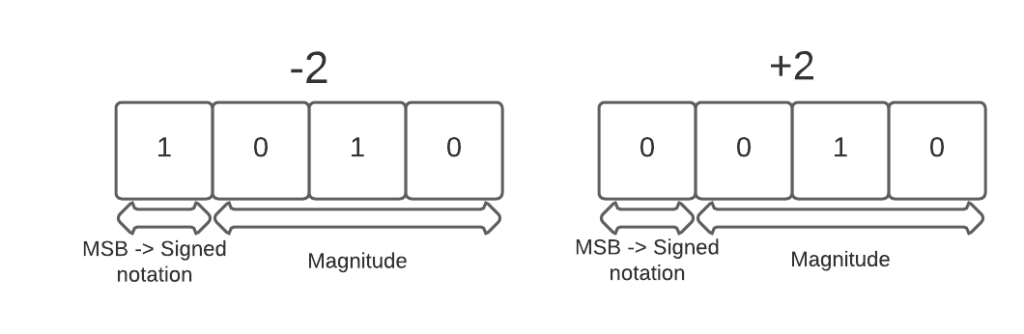
In this notation, the first bit is used to denote the sign of the number and rest is the magnitude of the number. This notation helps to easy the signed magnitude addition, since a particular bit is dedicated to the sign of the integer.
Under this, the MSB defines the sign by the following scheme:
- MSB = 1 => integer is negative
- MSB = 0 => integer is positive
2. Signed Magnitude Adder
A signed magnitude adder can add either a negative number to a negative number, or a positive number to a positive number, or a negative number to a positive number.
When a negative number is added to a negative number or a positive number to a positive number, there is no issue of what sign we will end up with in the end result (i.e. positive sign in positive number addition and negative sign in negative number addition).
But, when we add a negative number to a positive number, the question arises which sign to put. Remember we are taking into consideration the signed addition in digital design and not common mathematical addition.
Though it is quite similar to mathematical one, the main purpose of our brain storming on the trivial concept is to make hardware.
So, in order to make hardware we need to formulate a simple rule:
- If the numbers have same sign => then we need to preserve the sign and simply add the numbers
- And if they have different signs => then we need to find the smaller number, Subtract it from the bigger number and preserve the sign of the bigger number as the sign of the output that we get.
I think it sounds pretty clean and concise.
3. Verilog Code for Signed Adder
There are many ways to this in Verilog, I am going to show you one here:
module signed_addition(
	input wire [3:0] a, b,  // input 4 bit value
	output reg [3:0] sum    // output 4 bit value
   );
	reg [3:0] mag_a, mag_b, max, min;// intermediate values
	reg sign_a, sign_b, sign;//intermediate signs

	always @* begin
	  mag_a = a[2:0] ;// storing the magnitude in mag_a
	  mag_b = b[2:0] ;//storing the magnitude in mag_b
	  sign_a =a[3] ; //extracting the sign
	  sign_b =b[3] ; //extracting the sign
          // checking for larger one
	  if(mag_a > mag_b) begin// if magnitude of a is greator
		max = mag_a; //thus max = a
		min = mag_b; //min = b
		sign <= sign_a; //the sign of 'a' will be sign of sum
	        end
	  else begin // else
		max = mag_b; //max = b
		min = mag_a; // min = a
		sign <= sign_b;// the sign of 'b' will be sign of sum
		end
          // logic for addition using check on signs of numbers
	  if(sign_a == sign_b) begin // if both have same signs
		sum[2:0] = max + min; // sum is addition of a and b
		end
	  else begin // if they have different sign
		sum[2:0] = max - min; // sum is subtraction of a and b
		end
          //in the end the sum is concatenation of sign and magnitude
	  sum[3:0] = {sign, sum[2:0]};
	end
endmodule
The above code pretty much sums up all the discussion about the signed addition, we did above.
Of course, you can make it scalable by using parameters, but I think you might be able to do that on your own.
4. RTL view

The above is the RTL view of the design which we just wrote. If you closely look there is a comparator, a Adder, a Subtractor.
Also inside each boxes below with 3 input and an output we have this logic gates set up:

By now this might be clear to what the Signed Magnitude Adder does and looks like on a gate level. But how to check whether this will work or not?
For this we will be writing a testbench, though you can directly do the stimulation in the stimulator itself, it is good practice to write test benches for your design.
5. Testbench
Writing Testbench can become quite tricky sometimes. But fortunately for us this is not a problem now, as our main circuit is easy.
module signed_tb;
	// Inputs
	reg [3:0] a ;
	reg [3:0] b ;
	// Outputs
	wire [3:0] sum;
	integer i;
	// Instantiate the Unit Under Test (UUT)
	signed_addition uut (
		.a(a) ,
		.b(b) ,
		.sum(sum)
	);
	initial begin
	   #100;
	   a = 4'h0;
	   b = 4'h0;
	   for(i=0; i<15; i=i+1) begin
		// Initialize Inputs
	 	a = a + 4'h1 ;
		b = b + 4'h2;
	        // Wait 10 ns for global reset to finish
		#100;
		end
            //Add stimulus here
	end
endmodule
This would help us see the overall functionality of our circuit by seeing and analyzing the output stimuation.
NOTE: there are many ways in which you can write your testbench. Not only that but you can also create additional circuits for analyzing your signed magnitude adder.
Since, we are just making the signed Magnitude adder for now, So this should work fine.
Also, I will be writing on the additional circuits to test your Main circuit design, so stay tuned.
6. Stimulation
This is where we get to know whether our circuits are working as we expected.
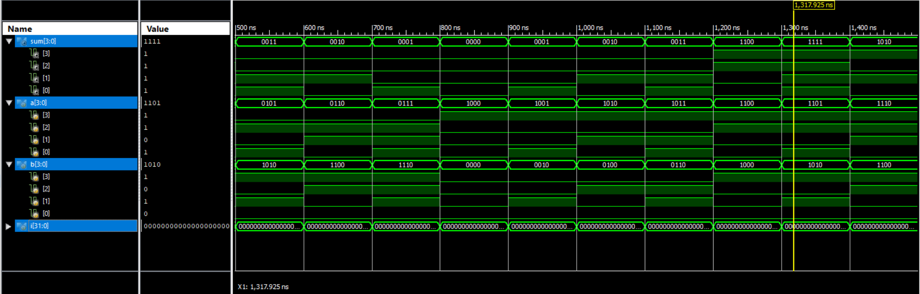
Great, this is what we wanted.😎
Keep Designing 🛠
